
In this project we do not use the 3D basic shape cube to describe the body of the wall anchor. To get a, we only have to take the square root: a = sqrt( c^2 / 2 ). If we now move the 2 to the other side of the equation, we are almost done: a^2 = c^2 / 2. So we can rewrite our formula to a^2 + a^2 = c^2 or 2 x a^2 = c^2. Since our triangle is in a square, we already know that the small sides are equal in length. In our particular case here, the long side of the triangle c is given and we are looking for the length of the small sides. We know that a^2 + b^2 = c^2 holds true in a right triangle. However, at this point, it won’t do anything when you copy-paste it into OpenSCAD, we need to add a bit more.Side_length = sqrt( pow(drill_hole_dm, 2) / 2 )
#OPENSCAD ROUNDED CUBE CODE#
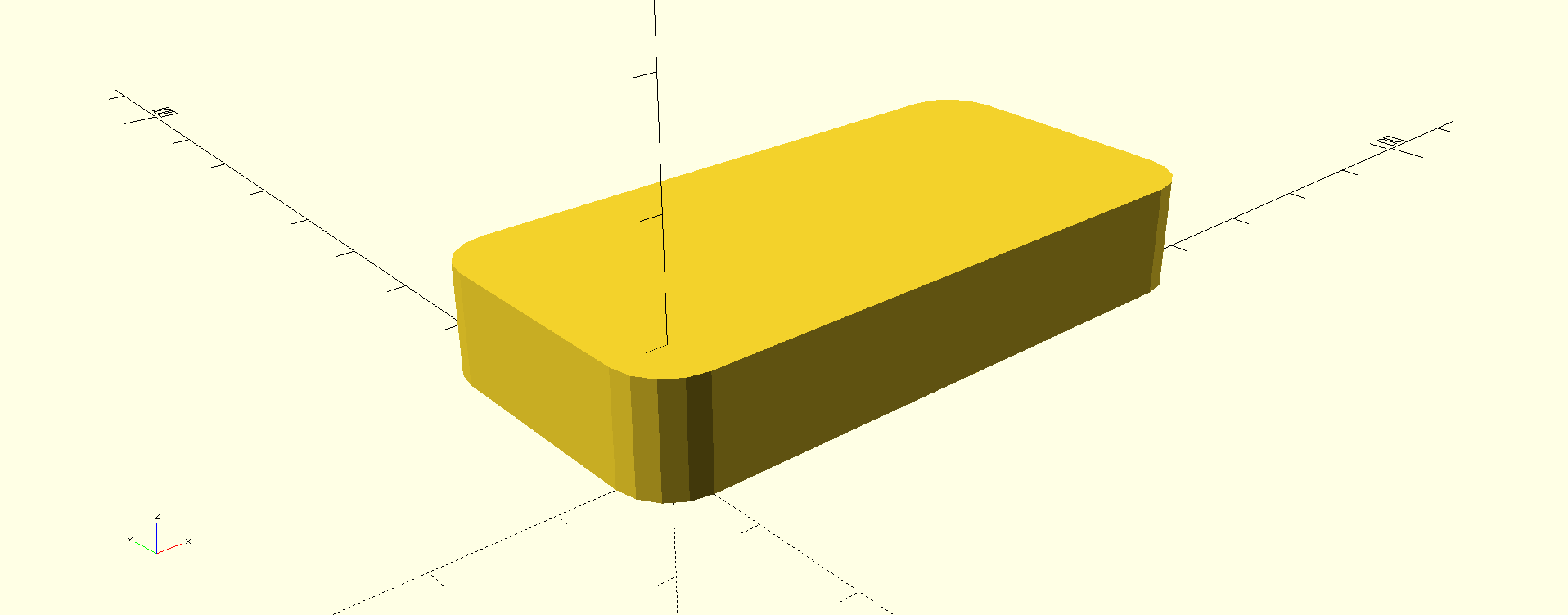
The module will be called ‘rcube’ and its code is below. And since we will be using this shape regularly, we will write a module (this is OpenSCAD’s term for something that’s usually called a method in other programming languages), which will create a cuboid with dimensions and edge curvature based on variables we enter. But in this case, cylinders will be perfectly fine.

However, if we wanted to have rounded corners not only in the projection view but on all edges, then we would have to use eight spheres instead of four cylinders (two spheres in each corner). When we apply the ‘hull’ function, we will get the required shape. These four cylinders will be the base for our cuboid. This function will create an object that tightly encompasses all of its child objects. Typically, this is generated in OpenSCAD using a ‘hull’ function. One of the most used constructs when designing models is a cube with rounded corners.
#OPENSCAD ROUNDED CUBE DOWNLOAD#
If you want to see the complete code, either scroll to the last two chapters or download the sample code from the last paragraph. Please note that throughout the article, I’m explaining various pieces of code separately to save space.
#OPENSCAD ROUNDED CUBE HOW TO#
So let’s take a look how to create a single model and modify it by changing a few variables. This is a typical task for OpenSCAD’s parametric design. Bigger things will require a more robust shape and probably also holes for screws, that will hold the brackets in place. For smaller and lighter devices, we require only a small and light bracket. Their shape and dimensions will be different for each device. In this picture, you can see a device mounted on the underside of a table using red colored brackets. They are exactly what we’re going to create today. Network switches, routers, USB hubs, card readers… thanks to the S-brackets, these things can be mounted on the underside of a desk, so they are always at hand, but they don’t get in the way. Today, I’m going to show you how to take advantage of this, and we will create another useful thing – an S-bracket.Īn S-shaped bracket is something I print quite often because I like to put all sorts of devices on the underside of tables, racks and so on. It’s a feature that allows you to quickly and easily change the design of a whole object just by modifying a few variables. One of OpenSCAD’s biggest strengths is the ability to easily incorporate parametric design. And I have also encouraged the readers to try and modify the values in the code to see how they affect the model’s shape. In my previous article, I’ve shown you how to create a spare part for an office chair using OpenSCAD.


 0 kommentar(er)
